

The new AdapTec TA comes with dual power output DC 5V and DC 12V. This accessory works as a power supply medium to provide power backup to FingerTec’s terminals with time attendance function. In the event of power failure, a DC 12V rechargeable battery sustains AdapTec TA’s power supply to ensure a longer standby time. Consisting of a power supply/power input as well as a power output module, AdapTec TA can also connect to other devices that utilize the similar power requirement of a DC 5V 2A. With a siren bell and relevant devices that facilitate the external siren feature, the new AdapTec TA supports DC 12V Siren and DC 12V rechargeable backup battery.
| Supports Rechargeable Backup Battery The AdapTec TA can connect to any DC 12V rechargeable backup battery, providing a power supply to ensure the FingerTec terminals will still function in an events of power failure. |
| Powers Up 2 Units of FingerTec Terminals The AdapTec TA can simultaneously power up 2 units of DC5V 2A and DC12V FingerTec terminals. You no langer need to add power points or adapters for 2 units of FingerTec terminals. |
| Supports DC 12V Siren It can power up the siren (max DC 12V 1A) to alert employees on start/stop working time, shift change etc. |
| Cleaner Installation with DIY Metal Casing Store the AdapTec TA and its backup battery in an exclusive FingerTec DIY metal casing, providing a neat installation. |
| UNDERSTANDING THE DESIGN |
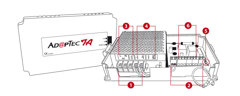
|
||||||||||||||||||||||||||||||||
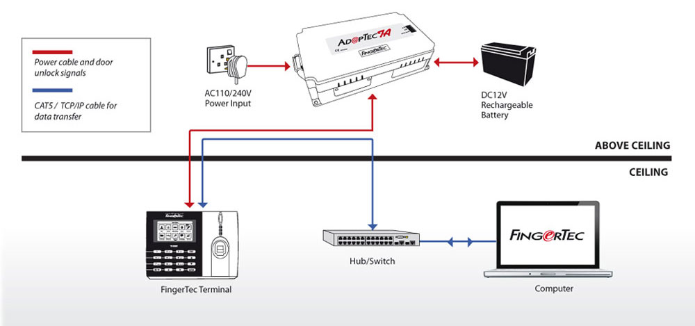
| Installation Diagram for illustration only * Optional | ||||||||||||||||||||||||||||||||
| SPECIFICATIONS | ||
| Surface finishing | Zinc alloy | |
| Dimension (mm) | 198 x 131 x 43 | |
| Weight (g) | 900 | |
| Input power | AC110 ~ 240V | |
| Output power | DC 5V 2A, DC 12V 1A, DC 12V 1A (Siren) | |
| Backup power | UPS or DC 12V rechargeable battery | |