|
02. Connection and testing of system components |
|
|
| |
Cabling
The first step is to consider the normal interface between the equipment and the wiring such as the wiring connectors, terminal blocks or the other methods by which the cables are to be terminated. Bad connections lead to high resistance and voltage drops. Be careful at these interfaces because so many problems are caused at these stages. |
| |
Equipments
Once the cabling has been terminated and proved satisfactory, it’s possible to test the equipment. All equipment should be confirmed as able to withstand air temperature o 0-40 degree C for internally sited equipment and -20 to 50 degree C for externally sited equipment. You can break down the test schedule into the following areas: |
| |
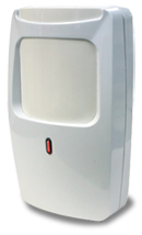
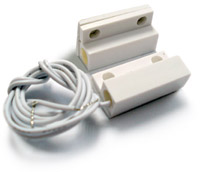
Perimeter Protection Hardware
This testing consists of hardware and locks such as closers, sensors, push-to-exit buttons and etc. |
| For the Perimeter Protection Hardware, 10 things you need to check for: |
| Correct alignment of all the hardware to ensure that they function properly. |
| Correct operation in accordance with the specifications of the hardware |
| Make sure that as the lock is energized or de-energized, it performs as specified for emergency purposes. |
| Test whether the locks failing in the correct fashion fail locked or fail unlocked |
| Manual overrides functioning smoothly and overcoming any electrical malfunction |
| Ensure that all sensors give the correct response to the door position |
| Check the operation of door closers to ensure they pull the door closed with the correct force. |
| Push-to-exit buttons should be verified for operation |
| Perform a test to prove that timers generate alarm activation when doors are open for longer than their preset period. |
| Prove that the door lock remains energized for the timed period. |
|
| |
 Tokens and Readers Tokens and Readers
During this check you need to make sure that verification of the token, credential or physical behavior characteristic is performed correctly. Carry out 6 steps below: |
| The token reader must reliably read the credential introduced to it. For fingerprint reader and face, register biometrics templates accordingly and test on their verifications. Register some cards and test the verifications to make sure that all readers and tokens function properly. |
| Different tokens should be tried |
| Don’t forget to try invalid transactions to make sure that non of the invalid transactions would allow access. |
| Authorized tokens should generate the correct response and output at the display. |
| Voided and forged tokens should be introduced to the hardware as well to ensure the correct output is generated. |
| Authorized tokens are to be signaled to and recognized by the central controller, |
|
| |
| Check that all the readers provide the following features: |
| An indication for access granted – For example in FingerTec fingerprint readers, once the fingerprint is read, the hardware will provide vocal indication i.e. Verified! Or for card, it’s the Oo..oo sound. |
| Variable time available for access to be made, if the system allows the door to be opened for 2 second after every verification, the electromagnetic lock should be on again after two second and alarm alerted. |
| Detection of physical tampering and, for readers fitted externally, protection against malicious damage. The use of enclosure is highly recommended and for FingerTec products, only fingers can touch the sensor and the keypads. No other parts are accessible. |
| Response within two seconds of the valid completion of the necessary entry procedure and relocking of an access point if it is not then used within a predetermined time. |
| Readers shall be securely mounted in a convenient position for the user adjacent to the access point, but proximity readers may be sited at any point where successful activation will occur. Don’t install reader far away from the door because the staff would take sometime to cross the door after verification is granted. |
|
| |
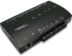
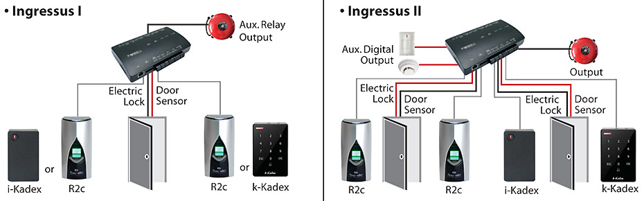
Controllers
Controller is the heart of the access control system being the processing unit that monitors and then controls the reader and tokens presented to it. Single door controllers have a more limited capability than local controllers used in multi-door system. To carry out the checks of the controllers, it is necessary to load the system software.
|
| Perform the tests as for tokens and readers to ensure correct response and the display of programmed messages |
| On activation of the reader the door hardware signaling should be enabled. |
| Inputs and outputs to ancillary equipment should respond as programmed. |
| Off-line operation should confirm to specification |
| In off-line checks should establish if tokens can still be read and doors unlocked. |
| Memory storage facilities and memory buffers should be verified with the controller offline. |
| Remote signaling should be generated as required according to the programmed parameters. |
|
 |
 |
| You also need to check that the controller installation adheres to the manufacturer’s
specified environmental conditions, which include: |
• Temperature
• Humidity
• Dust and other air contamination
• Vibration
• Electromagnetic interference |
| |
Cables
Cables carry different signals, it could be data, communication, alarm or power.
Inspections that need to be done include: |
| Visual inspections to make sure cables comply with the specifications |
| Ensure that no joints are made outside of junction boxes and that unapproved connection techniques are not used. |
| Check for damage to the cores of the wiring and confirm that there is no missing insulation or that it is stripped back too far. |
| No points in the wiring are to be stressed |
| Prove the consistency of the color codes |
| Ensure that the segregation of cabling from other cabling in the building is correct |
| Check for suppression being applied. |
| Check cables within containments and that conduit is grounded. |
| Verify the wiring routes are to the plans and follow the claimed routes |
| Ensure that the ambients of temperature that the cable is routed through cannot interfere with the performance of the wiring. |
|
|
|
| |
Power Supplies
Failure of the power supply or the cabling to it can cause a total closedown of the system unless standby batteries are provided.
For power supplies, please check the following: |
| The mains supply to the power supply should be correctly fused and be visually and electrically tested. |
| Supplies to the access control system should be proved to be identified at their source |
| The power supply should have the efficiency of the earthing confirmed. |
| Make sure that a UPS is in the location where maintenance can be easily carried out and that they are in a ventilated area, and installed in a location that’s secure from tampering |
|
| |
|
|
| |
Signaling equipment
This part of the equipment testing involves us with the signaling that may be local within the protected areas or to a remote monitoring point or central station. |
| Local signaling should prove that any warning device or visual monitoring equipment receives the correct response in according with the transmission of a signal from the access control system. |
| Any other security or building system or service integrated with the access control system should be verified as receiving an appropriate transmission |
| Door call units used with intercoms should be tested for audible and visual receipt at all appropriate points. |
| A check should be made with the remote monitoring point or central station that the message that is to be generated is received. |
|
| |
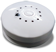
Ancillary equipment
Although certain ancillary equipment may have been verified in the test for other areas, this category includes mechanical and electrical sensors, booster power supplies and repeaters plus devices such as printers and VDUs. |
|
|
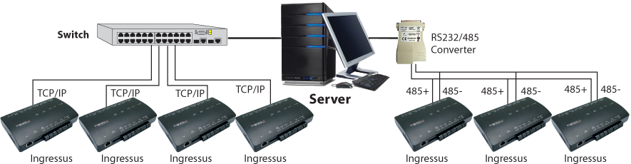
Communication equipment and software
This can form the final part of the equipment test schedule before the readings for the power circuits are logged. |
| All data must be checked for correct entry |
| All alarms must be correctly displayed |
| All access levels with the times of access allowed must be verified. |
| Operator levels are to be defined |
| Events must be shown exactly as they occur and as specified. |
| All automatic systems feature as specified. |
|